ˇß Description
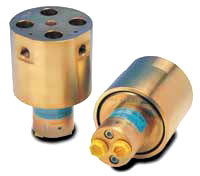
The HC8 was developed for applications
where intensified pressure up to 2,000 bar are required.
Operating like the HC2, the HC8 is a unique, self contained
device which boosts inlet pressure by up to a 20:1 ratio
without the use of external power. In addition, the HC8
maintains high pressure by automatically compensating
for consumption
of oil on the high pressure side. High pressure is directly
proportional to inlet pressure. The HC8 is compact in
size. The HC8 works at inlet pressure from 20 to 200 bar.
On standard versions maximum outlet pressure is 2,000
bar. Higher pressure is available on special request.
ˇß Inlet pressure
Inlet pressure 20-200 bar
ˇß Outlet pressure
2000 bar maximu
ˇß Return pressure to tank
PReturn as low as possible
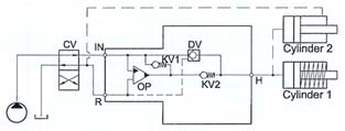
ˇß Intensification ratios
Outlet pressure PH = (PIN
- PReturn) ˇż i (Intensification)
ˇß Number of Intensification ratios
4 intensifications
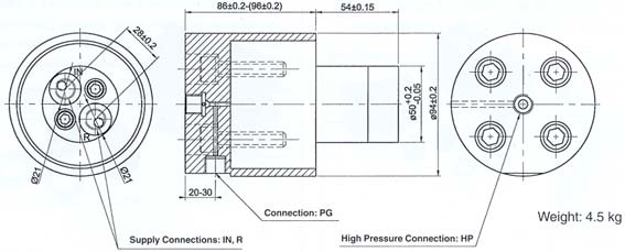
ˇß Mounting
Inline tube
ˇß Accessories
Pilot operated dump valve incorporated
Pressure gauge/transducer connection available
|