Home> Products > Rescue System > miniBooster > HC2

HC1 ---- HC2 ---- HC8


[The HC2 miniBOOSTER]

¡ß Description

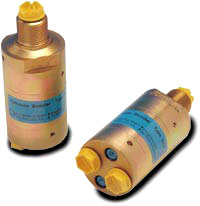
The HC2 is a compact unit weighing only 1kg. It is ideal for use in a variety of applications where building and maintaining high pressure is required. 
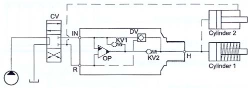
The HC2 raises supplied pressure to a higher outlet pressure and automatically compensates for consumption of oil to maintain the high pressure. Adjustment of the outlet pressure is carried out by varying the supplied pressure.

¡ß Inlet pressure
Inlet pressure 20-200 bar

¡ß Outlet pressure
800 bar maximum

¡ß Return pressure to tank
PReturn as low as possible

¡ß Intensification ratios
Outlet pressure PH = (PIN - PReturn) ¡¿ i (Intensification)

¡ß Number of Intensification ratios
11 different intensifications
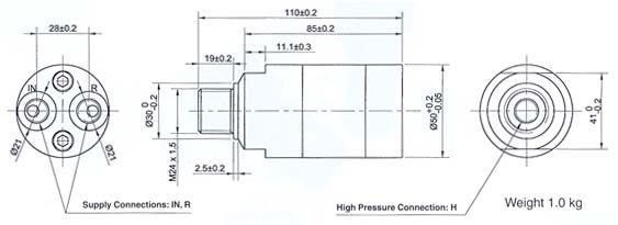
¡ß Mounting
Inline tube

¡ß Accessories
Pilot operated dump valve available


¡ß Flow Rates
Intensification factori
Max. Outlet flow l/min
Max. Inlet flow l/min
1.2
1.2
8.0
1.5
1.0
8.0
2
0.8
8.0
2.8
0.6
8.0
3.2
2.5
15.0
4.0
2.0
14.0
5.0
1.6
14.0
6.6
1.3
13.0
9.0
0.9
13.0
13.0
0.6
12.0
20.0
0.3
12.0
¡ß Max. tightening torque BSP

IN/R 1/4 BSP
H 1/4" BSP
with steel washer
4.0 da/Nm
4.0 da/Nm
with aluminium washer
3.0 da/Nm -
with cutting edge 4.0 da/Nm 4.0 da/Nm
¡ß Max. tightening torque UNF
IN/R 7/16-18" UNF
H 9/16-18" UNF
with o-ring
2.0 da/Nm
3.5 da/Nm
¡ß Dimensions
¡ß Functions

The basic operation is presented in the function diagram. The oil is led through the directional valve CV to the IN-port, where it flows freely through the check valves KV1 and KV2 to the high pressure side H. The oil will also flow freely through the DV-valve . In this situation a fast forward function to fill up the high pressure side is achieved . When the pump pressure is build up on the high pressure side H, the valves KV1, KV2 and DV will close. The end pressure will now be built up by the oscillating pumpunit OP. The unit automatically stops when the end pressure on the high pressure side H is established. If there is a pressure drop on the high pressure side due to consumption or a leakage, the OP will automatically work to maintain the end pressure.

¡ß Ordering a HC2

Model Intensification, i Dump Valve Connections
HC2 -   -   -  
see flow rate table A = (no) 1
B = (yes) 2

Ordering example of a HC2 with i = 4.0,
DV incorporated and BSP connections:
HC2- 4.0 - B - 1

Connection
IN,R
H
1
1/4" BSP
1/4"BSP
2
7/16-20 UNF
9/16-18 UNF