Home > Products > Hydraulic > miniBooster > HC5


[The HC5 miniBOOSTER]

¡ß Description
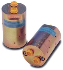
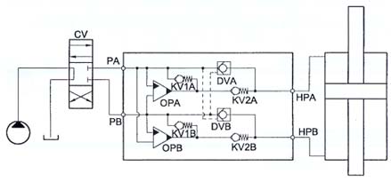
The HC5 is a double acting miniBOOSTER incorporating two separate intensification circuits. As the Function Diagram indicates, changing the position of the control valve CV switches intensification from one circuit to another. It is ideal for use in applications where high pressure is required in separate activation steps such as double acting cylinders, combination cutter spreader tools, etc. Like the HC2, the HC5 is a compact 
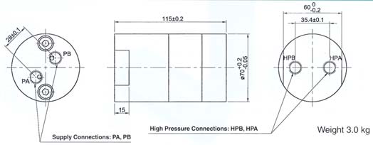
unit weighing only 3.0 kg.

¡ß Inlet pressure
Inlet pressure 20-200 bar

¡ß Outlet pressure
800 bar maximum

¡ß Return pressure to tank
PReturn as low as possible

¡ß Intensification ratios
Outlet pressure PH = (PIN - PReturn) ¡¿ i (Intensification)

¡ß Number of Intensification ratios
11 different intensifications

¡ß Mounting
Inline tube

¡ß Accessories
Pilot operated dumpvalves incorporated
High Pressure in two directions


¡ß Flow Rates
Intensification factori
Max. Outlet flow l/min
Max. Inlet flow l/min
1.2
1.2
8.0
1.5
1.0
8.0
2
0.8
8.0
2.8
0.6
8.0
3.2
2.5
15.0
4.0
2.0
14.0
5.0
1.6
14.0
6.6
1.3
13.0
9.0
0.9
13.0
13.0
0.6
12.0
20.0
0.3
12.0
¡ß Max. tightening torque BSP

IN/R 1/4 BSP
H 1/4" BSP
with steel washer
4.0 da/Nm
4.0 da/Nm
with aluminium washer
3.0 da/Nm -
with cutting edge 4.0 da/Nm 4.0 da/Nm
¡ß Max. tightening torque UNF
IN/R 7/16-18" UNF
H 9/16-18" UNF
with o-ring
2.0 da/Nm
3.5 da/Nm
¡ß Dimensions
¡ß Functions
The basic operation is illustrated in the function diagram. The oil is fed through the directional valve CV to port PA, flowing freely through the check valve KV1A, KV2A and DVA to the high pressure side HPA. In this condition maximum flow through the booster is achieved giving a fast forward function.
When pump pressure is reached on the high pressure side HPA valves KV1A, KV2A and DVA will close. The end pressure will be achieved by the oscillating pump unit OPA. The unit will automatically stall when end pressure on high pressure side HPA is reached. If there is a pressure drop on the high pressure side due to consumption or leakage, the OPA valve will automatically operate to maintain the end pressure. To operate the cylinder in the other direction simply change the position of the CV and the pressure will now be built up via OPB.
The intensification ratios of OPA and OPB can be determined independently so that different end pressures can be achieved from the same supply pressure.

¡ß Ordering a HC2

Model Intensification, iA Intensification, iB Connections
HC2 -   -   -  
see flow rate table see flow rate table 1
  2

Ordering example of a HC5 with i A= 4.0,
iB i= 5.0 and BSP connections:
HC5 - 4.0 - 5.0 - 1

Connection
IN,R
H
1
1/4" BSP
1/4"BSP
2
7/16-20 UNF
9/16-18 UNF